Most of us don’t stop to think very long about the threads on bolts and studs. But like all the component parts in your piping system, they are also contributing to the overall integrity and safety of your system. Let’s look at bolt and stud threads, and why thread protrusion and thread engagement are two keys to keeping your system safe.
ASME B1.1 (Unified Inch Screw Threads) states that the last effective thread of an externally threaded fastener occurs about three threads from the end of the bolt or stud. So, a stud or bolt is not effectively joined with the nut until the stud or bolt extends at least three or more threads beyond the end of the nut.
ASME B31.1 (Power Piping) states that all bolts shall be engaged so that there is visible evidence of complete threading through the nut or threaded attachment.
ASME B31.3 (Process Piping) states that bolts should extend completely through their nuts. Any which fail to do so are not considered acceptably engaged if the lack of complete engagement is not more than one thread. This standard forces you to look at the end of each nut and determine that there is not more than one nut thread open.
Why could this be problematic?
From the references above, we can see that thread protrusion and engagement criteria differ slightly depending upon the system application. When it’s time to inspect your system, watching for thread protrusion and engagement can be challenging. Quite often these systems are difficult to access. You may only be able to see them from a nearby platform. You’ll find that it is almost impossible to determine whether a flange is completely and properly engaged unless you can view the studs protruding through all the nuts on each side of the flange joint. So, stud bolt protrusion is a way of visually determining proper bolt-up without peering into the end of each nut. Many experienced pipe fitters see the value of this method of inspection and have adopted it.
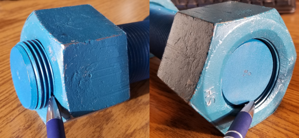
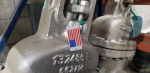
Right photo: No thread protrusion is non-compliant with ASME.
ASME B16.5 (Pipe Flanges) has a set of tables prescribing recommended lengths for studs and bolts of various classes. The table calculations are a summation of all the variables in a flanged joint: thickness, height of raised faces, gasket thickness and thickness of nuts. The added lengths for end points are mentioned, but not included in the total stud length shown in the tables. End points are the little bit where the threads are not yet fully cut.
Why could this be problematic?
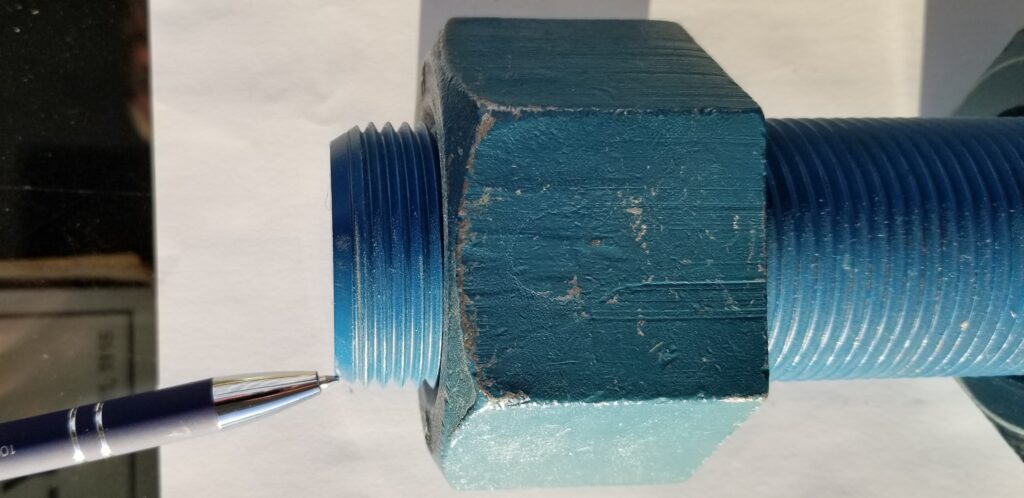
Lots of people don’t think about the end points of the studs. The end point (visible in the photo below) is the unthreaded part that generally protrudes beyond the nut. So, if the studs are ordered exactly in accordance with the table, they can end up with studs with no thread projection beyond the nuts. The Standard of New England Stud & Bolt Chart is a good reference.
Tip: Bolt and stud tables presume you are using a 1/16” gasket when bolting your flange. But if you are using a spiral-wound gasket it’s important to remember that spiral-wound gaskets are thicker. Therefore, if you are following the bolt/stud chart your bolt/stud will be a little short and you will need to order longer bolts/studs for spiral-wound gaskets.
A Note About Using Threaded Rod
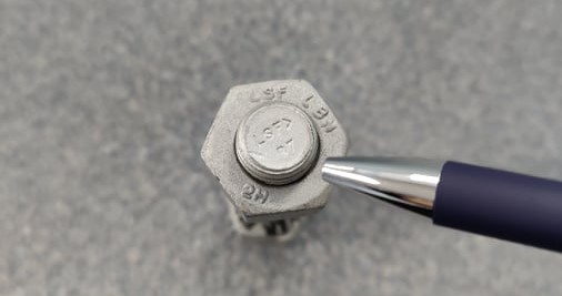
As you do your own research, you’ll find various interpretations regarding using threaded rod for studs/bolts. One of the issues with installing sheared threaded rod cut to usable stud lengths is that you have no identifiable markings on the studs except for the one end of the rod. If your piping system is constructed to an ASME standard this should not be allowed.
The Bottom Line
In summary, design engineers, suppliers, installers, and contractors all need to possess the conviction of keeping our systems safe and remembering to pay attention to thread protrusion and thread engagement is a small detail that adds to the integrity and safety of our piping systems.


